Hierarchical Electromagnetics
Fast electromagnetic designs and accurate full wave modelizations
The Hierarchical Electromagnetic Modeler is accurate from 0 frequency
Most commercial high frequency solvers are plagued by the well known low frequency breakdown problem
and they become unstable and inaccurate at lower frequencies. The Hierarchical Electromagnetic Modeler
is not affected by this problem and its modelization remains accurate from zero
to the maximum design frequency.
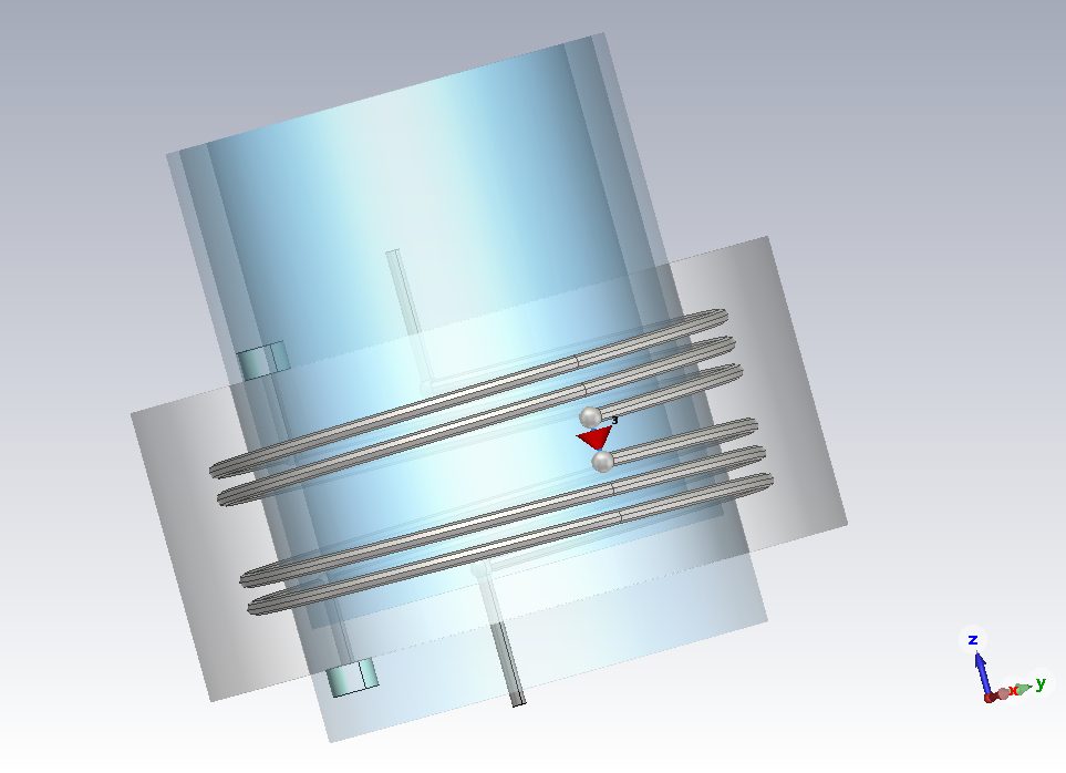
This capability is demonstrated considering the two pole helical filter shown in figure 1 which is
characterized by a capacitive inter-resonator coupling implemented by a planar capacitor on
alumina substrate. The helics are embedded in a rexolite dielectric which fills the entire cavity
apart a cylindrical quartz vessel that is filled of hydrogen. These details are related with
a peculiar application but are irrelevant for the purpose of the present analysis. This device has
been designed in the EmCAD enviroments exploiting fast procedures for filter tuning.
The electrical response simulated with the EmCAD code is reported in figure 2.
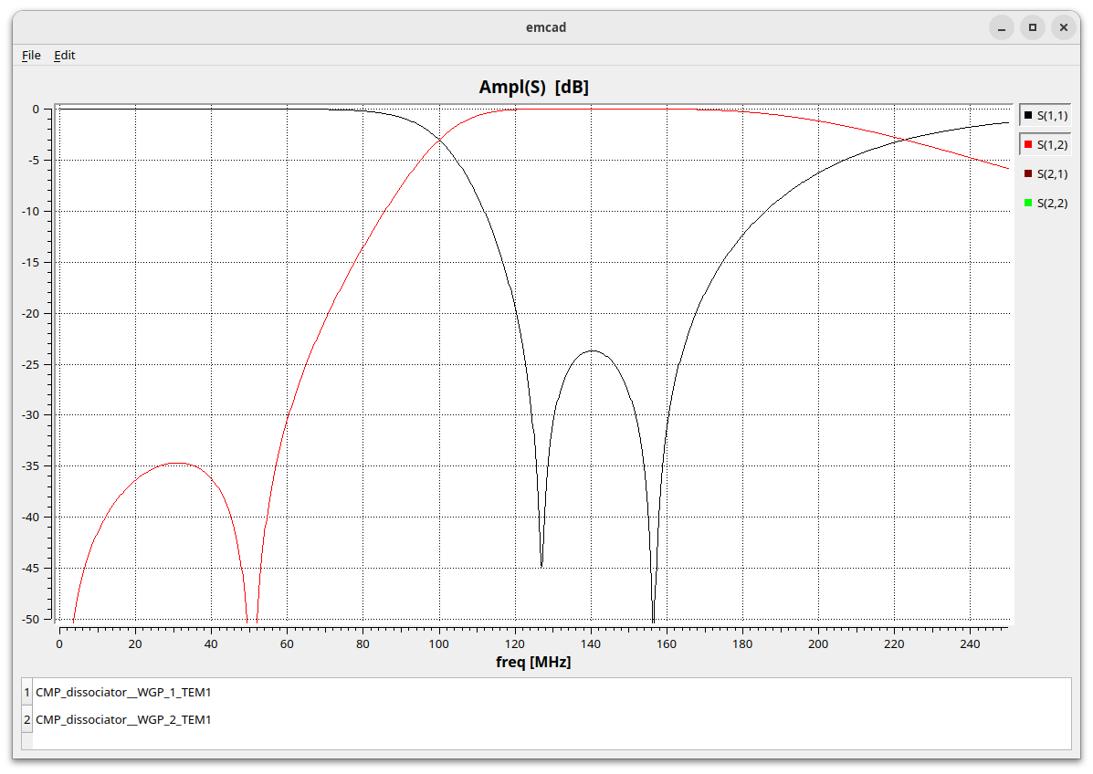
To make a cross check the same structure was simulated with CST Microwave studio but the result of this simulation
(shown in figure 3) doesn't match the EmCAD simulation.
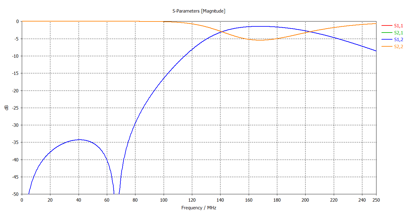
Usually the simulated responses of EmCAD and CST Microwave Studio agree very well but in this case there is a very big difference.
I was already aware that, due to the low frequency breakdown problem, CST Microwave studio can't provide accurate simulations
of small capacitors at very low frequencies. The low frequency breakdown problem is not related with the absolute frequency value
but with the dimension/wavelength ratio associated with the device.
Having a thickness of 25 mil (0.635 mm), the alumina capacitor used for inter-resonator coupling is much smaller than
the wavelength (about 2 meters) at the filter frequency. It was therefore supposed that the observed disagreement should be ascribed
to an inaccurate CST simulation of the small capacitor.
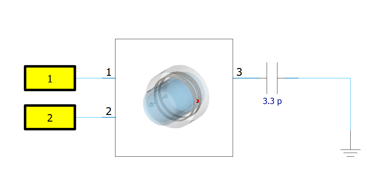
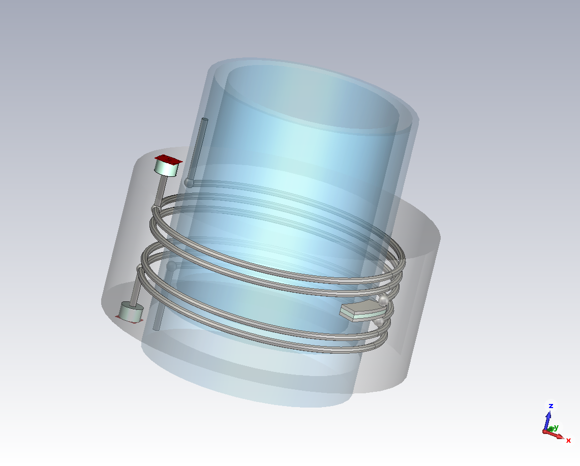
To check this hypothesis the alumina capacitor was replaced, in the CST simulation, with a discrete port leading to the 3 port structure
shown in figure 4. The associated equivalent circuit has been reconnected to a lumped capacitor inside the schematic environment
provided by CST Microwave Studio as shown in figure 5.
The capacitor value of 3.3 pF is computed with a simple formula considering area and thickness of the alumina capacitor.
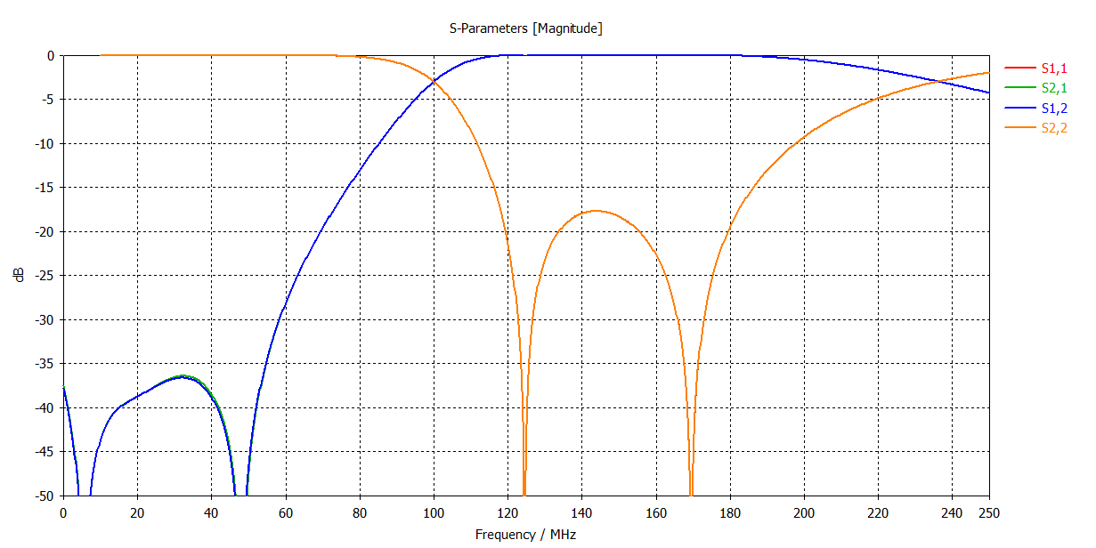
The electrical response of the circuit depicted in figure 5 (shown in figure 6) is not identical but quite close to
the full wave response computed with the EmCAD code (shown in figure 2). The small discrepancy has probably to be ascribed
to the geometrical differences introduced in the removal of the alumina capacitor.
